 Pool countercurrent
 Pool countercurrent
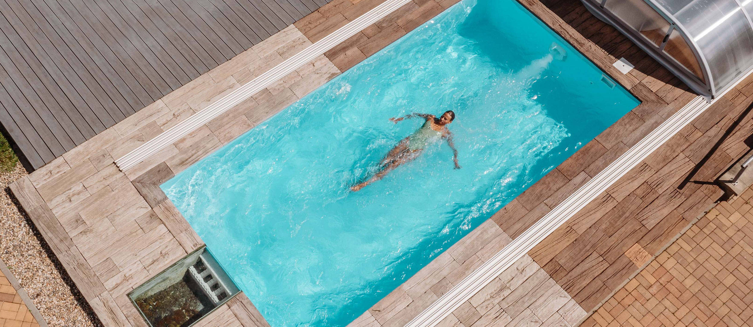
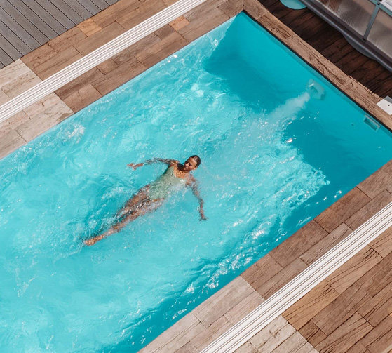
Would you like to swim in your own Olympic-sized pool, but it won't fit your garden? The ELEGANCE countercurrent is just the thing for you. As a consequence, you can constantly push the limits of your possibilities and train your swimming endurance even in a pool with minimal dimensions.
Easy control and smooth performance directly from the pool
Ideal for both indoor and outdoor pools
Suitable for fitness swimming or simply for water fun
It doesn't affect the aesthetic side of the pool
Basic description
Specifications
A simple, aesthetic, yet robust and powerful device, that above all, is characterised by its affordability. This accessory ranks among the so-called functional pool accessories. It's positioned on the pool wall. The benefit of countercurrent to the pool is easy control - you can control the air intake and countercurrent switching directly from your pool with the help of an electro-pneumatic switch, which is located directly on the countercurrent mask's body.
The countercurrent makes the enjoyment of swimming an even more pleasant experience and you no longer have to visit a public swimming pool to swim actively. You don't have to share the unique moments of relaxation with anyone, you'll also improve your physical condition and your children will surely be delighted too.
Technical specifications of the Elegance countercurrent
| Elegance 70 | Elegance 80 | Elegance 95 | |
|---|---|---|---|
| Tension | 230 / 400 V | 400 V | 400 V |
| Performance | 70 m3.h-1 | 80 m3.h-1 | 95 m3.h-1 |
| Power consumption | 2,2 kW | 3 kW | 4 kW |
| Nozzle diameter | 40 mm | 40 mm | 40 mm |
| Pipe diameter | 75 mm | 75 mm | 75 mm |
Countercurrent location
A motor (pump) is part of the countercurrent equipment. The pump should be placed as close as possible to the pool for maximum performance. The optimal distance is around 1 metre. It's ideal to place the countercurrent together with other pool technology directly in the pool equipment shaft. We don't recommend installing the pump further than 15 metres from the pool. The pump is not self-priming. Therefore, it's important that it's placed below the pool water level. You must ventilate the equipment technological room adequately, you can also use a fan, to prevent condensation. This will ensure correct operation of the device.
Countercurrent attachment
The countercurrent body contains 2 holes of unequal size. Discharge (smaller) and suction (larger). You must position the countercurrent body so that both openings are vertical and the discharge side is positioned higher than the suction side. Install the countercurrent device so the centre of the nozzle opening is at least 30 cm below the water level depending on the pool type.
Countercurrent body assembly
The Elegance countercurrent is suitable for use in all types of pools. However, the assembly itself differs slightly depending on the type of pool in which the countercurrent is installed.
Placing in concrete
Fit the countercurrent body and the hoses together (it's ideal to glue the hoses), then slide everything into the equipment's technological area (shaft). Avoid the hose ends making contact with the concrete. Install according to Figure 2a (top left) in a hole in a concrete wall or in a formwork for concreting without flanges and seals. Once the countercurrent body is fixed to the wall, follow the procedure described below in this manual. The next step is the pneumatic and air lines connection.
Placing in concrete pools with foil
When assembling the countercurrent body in the wall of the concrete pool with foil, proceed in accordance with the instructions above - chapter "Where is the countercurrent placed?". Once you've attached the countercurrent body to the pool wall, you can start installing the countercurrent seal and flange as shown in Figure 2b.
Attach the gasket to the countercurrent body with 2 screws and tighten them (don't tighten the screws completely). Note that the pool foil can be placed between two seals. Finally, attach the flange. Don't forget to tighten the screws and then cut the foil from the inside of the flange. Then you can proceed in connecting the air and pneumatic lines. You'll find the procedure below.
Placing in a panelled or sheet pool with foil
Firstly, it's necessary to cut a hole with a diameter of 270 mm in the pool wall so that the centre of the nozzle is located approximately 30 cm below the water level, as mentioned above in the chapter "Where is the countercurrent placed?". Insert the countercurrent body into the prepared hole from the inside of the pool. Fix it to the pool wall with 8 self-tapping screws as shown in Figure 2c.
Fix the seal to the countercurrent body with 2 screws and tighten the screws (don't tighten them completely). After installing the foil, fasten the flange and don't forget to tighten the screws. Then you can cut the foil from the inside of the flange. When connecting the air and pneumatic lines, proceed in accordance to the instructions below.
Placing in a prefabricated pool
This type of assembly is used for so-called prefabricated pools. For example, these include laminate or polypropylene pools. When placing it in this type of pool, a hole with a diameter of 230 mm must be made. When making the hole, bear in mind that the centre of the nozzle must be located at least 30 cm below water level (depending on the pool type, see chapter "Where is the countercurrent placed?".
Place the seal on the outside of the pool wall. This creates a template based on which you will make the holes for the 16 flange screws. From the outside of the pool, prepare a countercurrent body. From the inside, tighten the flange using the screws as shown in Figure 2d. Now proceed to the next step - connecting the air and pneumatic lines.
Air line connection
Place a non-return valve on the hose that's intended for the air line. It's important to install the non-return valve on the technological area's wall in a manner to prevent the suction of dirt. Attach the flexible tube to the end - push it into the nozzle inside the countercurrent body.
Connecting the pneumatic line
Pass the end of the pneumatic switching tube through the hole in the countercurrent body. Tighten it with a grommet and connect it to the pneumatic switch. The switch is located on the upstream end.
Front cover installation
The complete front cover is already assembled except for the transparent pneumatic tube. It's already an integral part of the countercurrent body. Follow the instructions below for front cover installation:
-
Slide the transparent tubing onto the air button mandrel and plug it in.
-
Connect the hose and insert it into the front cover nozzle.
-
Attach the complete front cover and the countercurrent body and make sure that the ring is definitely inserted into the mouth of the discharge hole (by 75 mm).
- Tighten the four screws. Once the screws are tight, the front cover is ready for use.
Minimum space requirements for device installation
Before installing the device itself, it's necessary to take the dimensions of the technological area (shaft) into account, where the countercurrent will be located. Make sure you don't run out of space when mounting the pump.
For installation, you need a technological area with minimum dimensions of: 75 x 142 x 90 cm (width x length x height).
Correct use and adjustment of the ELEGANCE countercurrent
Your pool becomes a place of rest and relaxation once the countercurrent is built in. A water current or a water current with air, which is created by a countercurrent, is responsible for inducing a pleasant feeling. You can start the countercurrent directly from the pool by pressing the pneumatic switch. Whether the countercurrent will drive a stream of water into the pool or a stream of water with air depends on the front nozzle settings.
Water stream:
The water stream is controlled and formed by an internal nozzle. Maximum water-flow can be achieved by turning the inner nozzle to the left. Likewise, turning the nozzle to the right will reduce the water-flow.
Water jet with air:
You can set the water-flow strength according to the above instructions. An external nozzle is used to regulate the air intensity that is added to the water-flow. By turning it again, you reduce or increase the air-flow intensity.
ELEGANCE Countercurrent Components List
1. pneumatic switch
2. pneumatic switch tube
3. face screw (front)
4. countercurrent front cover
5. ball external
6. air supply regulation nozzle
7. support ring
8. water supply regulation nozzle
9. inner ball
10. nozzle self-tapping screw
11. nozzle seat housing
12. O-ring
13. air tube (flexible)
14. pneumatic tube grommet
15. Grommet O-ring
16. flange bolt
17. flange
18. seal
19. countercurrent body self-tapping screw
20. countercurrent body
21. air line hose
22. air intake - check valve
Electric installation
Electrical installation should only be carried out by an authorised and certified technician according to generally applicable standards. The main power supply voltage must be identical to the label data, which is located on every device. Make sure that all metal parts of the device are correctly earthed.
The electrical characteristics regarding the fuse elements and their regulations must be in accordance with those given for the motor to be protected with the given operating conditions. All manufacturer's recommendations and instructions on the label must be followed.
If you have a device model with a three-phase motor, pay attention to the so-called connecting terminals between the motor windings being correctly connected. Their connection must be done in a so-called star. All wires (input and output) that are brought out of (into) the distribution box must be routed through grommets. For this reason, you'll prevent moisture and dirt from entering the distribution box. The wires must have suitable connection terminals.
Electro-pneumatic countercurrent switching (distributor) mustn't exceed a distance of 7 metres from the pneumatic switch. The pneumatic switch is located at the head of the countercurrent. The switch must be installed above the pool water level and must be located in a dry location. The pneumatic tube is connected to the electro-pneumatic switch, which is located on the electro-pneumatic switch (switchboard). It's extremely important to make sure that the tube is not bent or damaged anywhere.
The electro-pneumatic panel composition:
- motor protection
- electro-pneumatic switch
- control fuse
All these components should be housed in a waterproof plastic box with an IP55 degree of protection.
